Logic gates are the building blocks of digital electronics and are fundamental to how computers, mobile devices, and various other technologies operate. They play a crucial role in performing logical operations that form the foundation of binary computing systems. If you’re interested in understanding how logic gates work, their types, and how they impact digital design, this article will guide you through the key concepts, functions, and applications.
Logic gates perform basic logical functions on one or more binary inputs to produce a single output. They use binary values, typically represented by 1 (high) and 0 (low), to control decision-making processes in digital circuits. From controlling simple circuits to complex processing in microprocessors, logic gates are essential to virtually all modern electronics. Let’s dive into the different types of logic gates and their important roles in digital circuits.
What Are Logic Gates?
Logic gates are devices that execute Boolean functions, which are mathematical operations based on binary inputs. They process binary data in digital circuits to control the flow of electricity and perform logical operations such as AND, OR, NOT, XOR, and more. A logic gate operates by taking one or more binary inputs and producing an output based on a predefined logical rule.
The core of any logic gate is its ability to interpret these binary values and make decisions about the output based on the conditions of the input. A set of logic gates is often used together to form more complex circuits, which can add functionality and decision-making ability to a digital system. To gain a deeper understanding of the logic behind these gates, you can use a truth table generator to analyze how each gate operates with different input combinations.
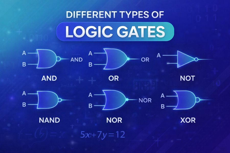
AND Gate: The Foundation of Logical Conjunction
The AND gate is one of the simplest and most commonly used logic gates. It operates on the principle of logical conjunction, meaning that it outputs a high signal (1) only when all its inputs are high (1). If any of the inputs are low (0), the output will be low (0). This makes the AND gate a crucial building block in digital logic design, where conditions must be met simultaneously for an action to occur.
For instance, in a digital circuit that controls a security system, the AND gate ensures that multiple conditions must be satisfied before triggering an alarm. If any of the required conditions are not met, the alarm will not be activated. You can explore how to make a truth table to understand the behavior of the AND gate with different input combinations.
OR Gate: The Disjunction Operator
In contrast to the AND gate, the OR gate operates on the principle of logical disjunction. It outputs a high signal (1) if at least one of its inputs is high (1). The output is only low (0) when all inputs are low (0). This makes the OR gate useful in scenarios where any condition being met is sufficient to trigger an action.
For example, in a simple traffic light control system, the OR gate could be used to trigger a “green light” when either one or both of the sensors detecting vehicle presence is activated. Understanding the functionality of the OR gate through its truth table is key to applying it effectively in various digital systems.
NOT Gate: Inversion and Signal Control
The NOT gate, also known as an inverter, is a logic gate that reverses the state of its input. If the input is high (1), the output will be low (0), and if the input is low (0), the output will be high (1). The NOT gate is crucial in digital systems where signal inversion is required for circuit logic or control.
This gate is often used in situations where a condition must be negated, like turning off a system when a particular signal is active. A classic example can be found in the operation of a NOT gate in a reset circuit, where it inverts the signal to reset or disable components.
NAND Gate: The Negation of AND
The NAND gate, which stands for “NOT AND,” is a combination of the AND gate and the NOT gate. It operates similarly to the AND gate but with the output inverted. In other words, it produces a low (0) output only when both inputs are high (1). For all other input combinations, the output is high (1). The NAND gate is highly favored in digital design due to its versatility and the fact that it can be used to construct any other type of gate, including the AND, OR, and NOT gates.
One reason NAND gates are widely used is that they can help reduce the complexity of circuit design. You can learn more about how to construct a truth table for NAND gates and explore its significance in digital circuits.
NOR Gate: The Negation of OR
The NOR gate is the complement of the OR gate. It performs the logical operation of OR but inverts the output. This means the NOR gate will only produce a high (1) output when both of its inputs are low (0). In all other cases, the output will be low (0). The NOR gate is useful for creating circuits that need to generate outputs when no conditions are met, such as in certain fail-safe systems or when zero input is expected.
Like the NAND gate, the NOR gate has the unique feature of being functionally complete, meaning it can be used to build all other types of logic gates. The ability to combine NOR gates for creating other logic circuits is part of what makes them essential in digital design.
XOR Gate: Exclusive Or for Decision-Making
The XOR (exclusive OR) gate performs a logical operation that is slightly more complex than that of the OR gate. It outputs a high (1) signal when the number of high inputs is odd, and a low (0) signal when the number of high inputs is even. This makes the XOR gate useful for operations where the condition must only be true when inputs differ.
For example, XOR gates are used in error detection and correction circuits, where the system needs to distinguish between two different inputs, such as in the case of parity checking. The XOR gate’s ability to identify differing inputs plays a crucial role in data transmission and secure communications.
XNOR Gate: The Complement of XOR
The XNOR gate is the opposite of the XOR gate. It outputs a high (1) signal when both inputs are the same, and a low (0) signal when the inputs differ. This makes the XNOR gate useful in equality checking, such as determining if two binary values are identical.
In various control systems, the XNOR gate can be employed to ensure that multiple signals match before triggering an output. This is particularly helpful in security systems where input validation must occur before access is granted.
Applications of Logic Gates in Digital Systems
Logic gates have a wide range of applications in the real world. From simple operations like binary addition to complex functions in microprocessors, they are at the heart of virtually all digital systems. Some common applications include:
- Digital Clocks: Logic gates help synchronize digital clocks, where precise timing is essential.
- Microprocessors: Logic gates form the core of microprocessors that control complex calculations and decision-making processes in computers and smartphones.
- Control Systems: Logic gates are used to manage and control industrial systems, security systems, and other automated processes.
These applications demonstrate the versatility and importance of logic gates in digital design and modern electronics.
Conclusion:
In conclusion, logic gates form the foundation of all digital circuits and electronic systems. By understanding the different types of logic gates, their truth tables, and real-world applications, you can better appreciate the underlying principles that power modern technology. Whether you’re a student learning about digital electronics or a professional working with complex digital systems, mastering logic gates is crucial to developing efficient and functional designs.
Each gate has its unique characteristics and applications, with essential roles in everything from computational tasks to automated systems. To better understand how each logic gate functions with different inputs and outputs, you can utilize a truth table generator for a hands-on exploration of logic gate behavior.